Table of Contents
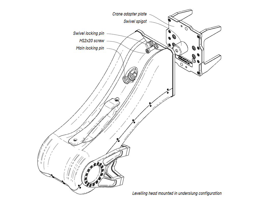
- Install the crane adapter plate
- Mount the Levelling head by sliding it onto the swivel spigot. It can be mounted in either overslung or underslung configuration.
- Push the button on the main locking pin and pull out the main locking pin.
- Slide the swivel bearing onto the swivel spigot.
- Push the button on the main locking pin and push the pin in. Make sure the main locking pin is correctly seated. When pulling the main
locking pin there shouldn’t be more play than 3mm (1/8”). If the main locking pin doesn’t snap into place, make sure the Levelling head is
pushed back all the way on the swivel spigot.
- Make sure the swivel locking pin is locked in place and the head can’t be turned.
- Lock the Levelling head by fastening the two M12x20 screws, one at the top, one at the bottom.
- WARNING DO NOT USE THE LEVELLING HEAD WITHOUT THE TWO FASTENING SCREWS
Doing so, can lead do severe damages to the crane it is mounted on and to anyone who’s near the crane. Kornercrane Inc. does not hold
liability if the Levelling head is mounted incorrectly or in any other way than described in this manual.
- Before using the Levelling head it needs to be referenced
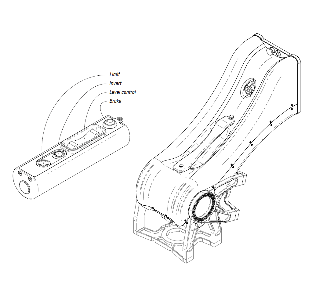
- When the head is in packing mode press the invert button once. The Levelling head goes into underslung mode and levels the cradle using it’s internal inclinometer. Make sure to keep the crane stationary while the head is referencing.
- If it is desired to use a different reference point move the head using the level control rocker.
- Go ahead and mount the payload now - the Levelling head is ready to use.
- CAUTION When the payload, make sure to lock the Levelling head by pressing the lock button. Ensure the crane can’t boom up or down by properly securing it with straps according to the manufacturers manual.
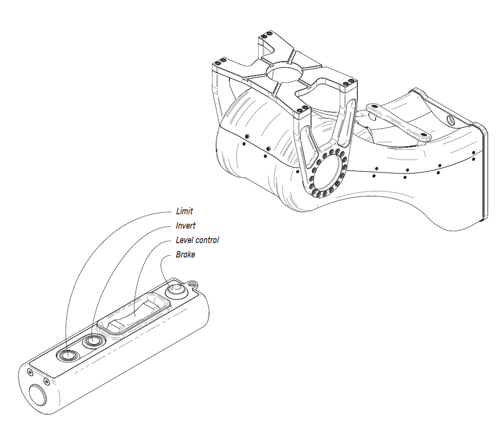
- To gain extra lens height the Levelling Head can be mounted upside down.
- When the head is in packing mode press and hold the invert button. The Levelling head goes into overslung mode and levels the cradle using it’s internal inclinometer. Make sure to keep the crane stationary while the head is referencing.
- If it is desired to use a different reference point move the head using the level control rocker.
- Go ahead and mount the payload now - the Levelling head is ready to use.
- CAUTION When the payload, make sure to lock the Levelling head by pressing the lock button. Ensure the crane can’t boom up or down by properly securing it with straps according to the manufacturers manual.
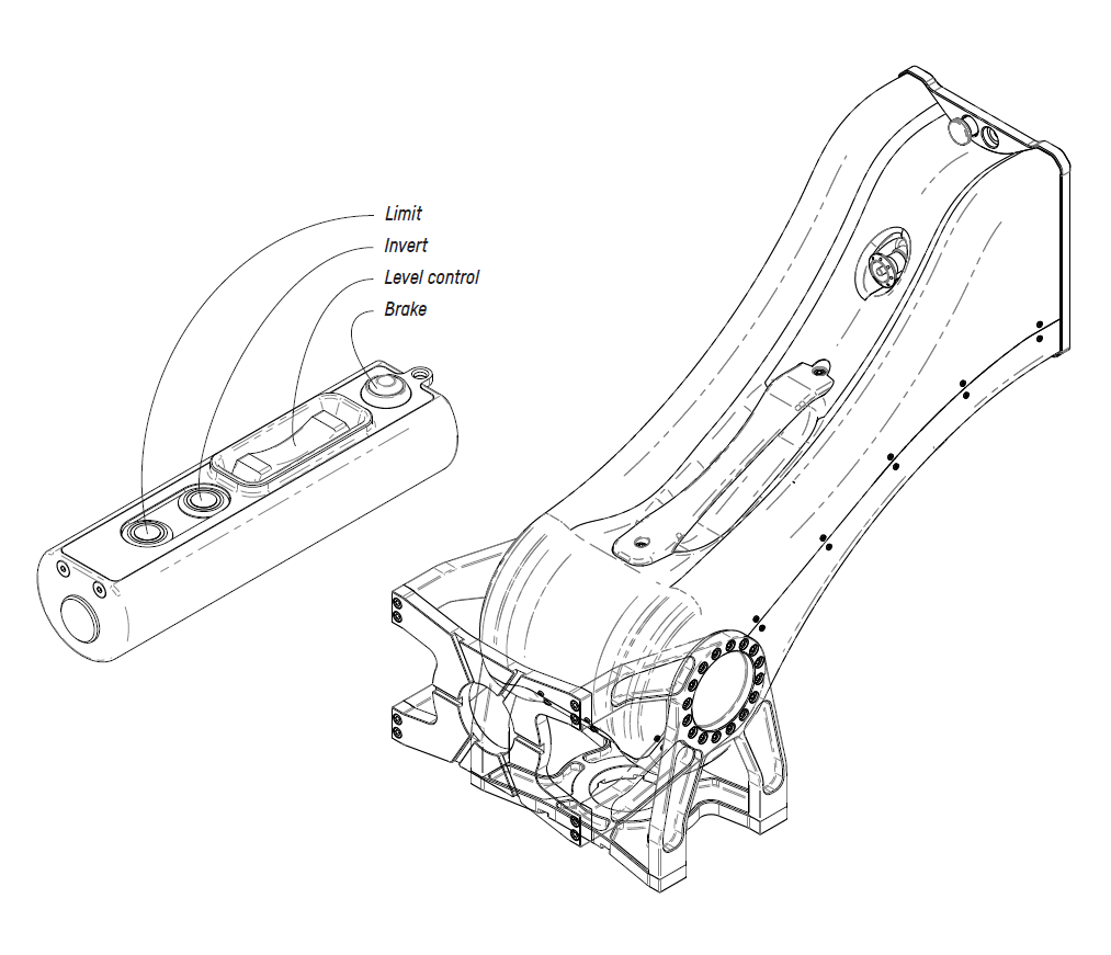
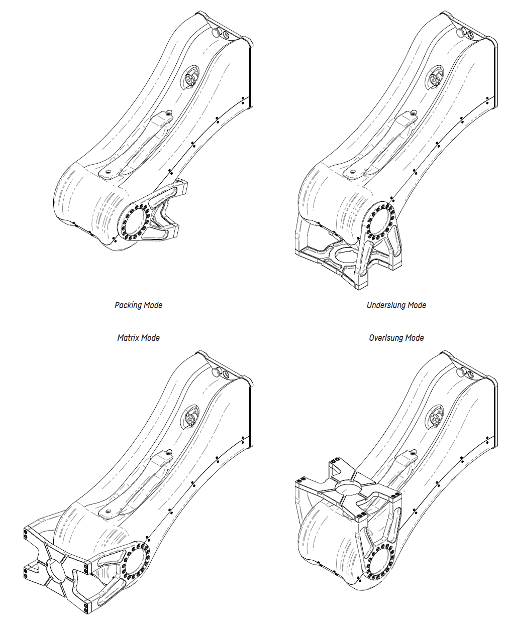
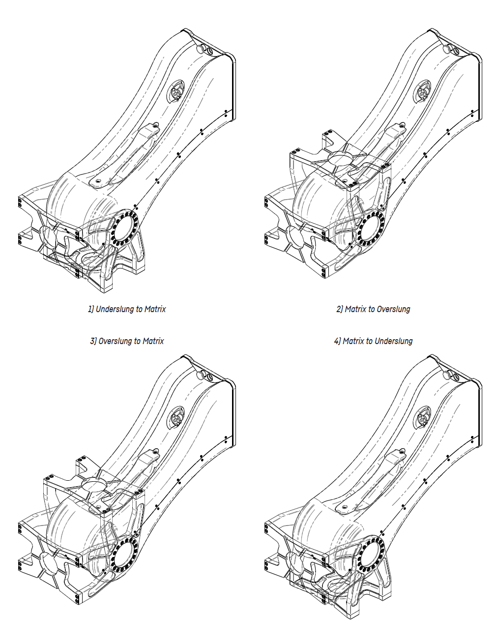
- The Levelling head offers 3 different operation and one packing mode. When powering up and referencing the Levelling head it automatically goes into the underslung mode.
- To change from underslung to Matrix mode, press the invert button once. Now the head moves 90 degrees (from the referenced level)
- In Matrix mode, the Levelling head still maintains level when booming the crane up or down. If this behaviour isn’t desired, the position of the Levelling head can be locked with the brake button. When the Levelling head is locked off, the red LED on the lock button lights up. Now the internal break engages and the levelling head doesn’t actively maintain level anymore.
- To toggle between modes, press the invert button again. The sequence is: underslung - matrix - overslung - matrix - underslung.
- To prepare the Levelling head for packaging press the limit and invert button at the same time to move into the heads packaging mode.
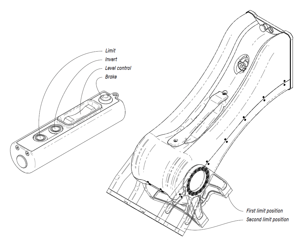
- The Levelling Head has two internal limits set that can’t be overridden - those are the end stops, so the Levelling head doesn’t crash itself. However, depending on the payload mounted, there can be the necessity to set user limits.
- Go to the first position where a limit needs to be set using the level control rocker.
- Press the limit button. It doesn’t matter which position is set first. The Levelling head automatically adjusts the limit window to be inside the two set limit positions.
- Go to the second position where a limit needs to be set using the level control rocker.
- Press the limit button again. Now the range of motion is limited to the sector between the two limit positions. An active limit is indicated by the LED on the limit button.
- To remove the limits, press and hold the limit button.